A quick note before you read further. This post is the culmination of my learnings in chapter 1 of the online course 'Build a Modern Computer from First Principles: From Nand to Tetris'. If you are taking this course and don't want to see spoilers for the chapter 1 project I would recommend pausing on this post and coming back after you've completed the project. If this doesn't apply to you, please read on 😀.
Elementary Logic Gates
A logic gate is essentially a logical operation that is performed on one or many binary inputs resulting in binary output. Logic gates are the building blocks of the technology that we use every day. They act as electronic switches in hardware and when composed can result in complex logic circuits resulting in things like registers and computer memory.
Today we are going to be focused on a handful of logic gates which are referred to as elementary logic gates. These gates represent the fundamental logic gates that can be used to build larger and more complex circuits. The gates are as follows.
- NAND
- NOT
- AND
- OR
- XOR
- MUX
- DMUX
In order to visualize the result of logic gates based on given inputs, we use a truth table. Truth tables consist of the logic gate input(s) as well as the resulting output for each input. Here is an example of the truth table for the NAND gate. As you can see there is a column representing each input a, b and a column for the output out.
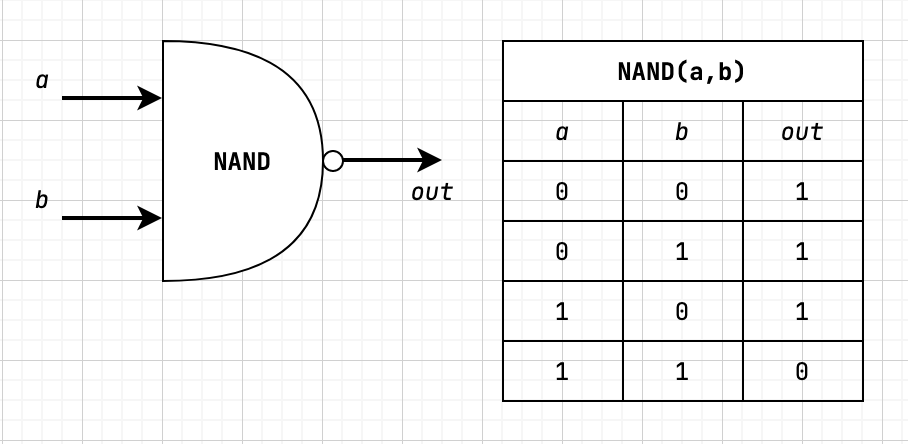
The interesting thing about these elementary logic gates is that they can all be implemented from NAND gates. So for the purpose of this post (and the referenced course above) the NAND gate will be considered a primitive gate we can use to construct all other logic gates.
With all of this in mind let's take a look at how Boolean Functions relate to elementary logic gates.
Boolean Functions
So far we've focused on logic gates, which happen to be physical implementations of boolean functions. At its core, a boolean function is a function that operates on binary inputs and returns binary outputs. Boolean functions play an essential role in the specification, construction, and optimization of computer hardware.
All boolean functions have a canonical representation which means that the function can be expressed by at least one boolean expression. The way that we determine the canonical representation can be broken down into a few steps.
- Identify all of the truth table rows that output 1.
- For each row in step 1, we
ANDtogether each literal input (a 1 is left alone and a 0 needs to be negated) to create a term - Finally,
ORtogether all of the terms constructed in step 2 resulting in a boolean expression equivalent to the truth table
Let's use the NAND truth table shown previously and the steps above to determine the canonical representation.
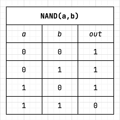
- Rows resulting in
1are 1, 2, and 3. - Now we need to create a term for each row by
AND-ing together each literal to result in1.(NOT a) AND (NOT b)(NOT a) AND ba AND (NOT b)
- Now we need to
ORall the terms to get the boolean expression.(NOT (a AND b)) OR ((NOT a) and b) OR (a AND (NOT b))
So with all of this done, we can say that the canonical representation is NAND = (NOT (a AND b)) OR ((NOT a) and b) OR (a AND (NOT b)). This exercise also demonstrates that all boolean functions can be expressed with AND, OR, and NOT operators. Since we can express each of the operators with NAND, this also means that every boolean function can be expressed with NAND as well.
Elementary Gates as Boolean Functions
In the following subsections, we will be seeing diagrams that include a graphical representation, truth table, and boolean function each representing the logic gate being covered.
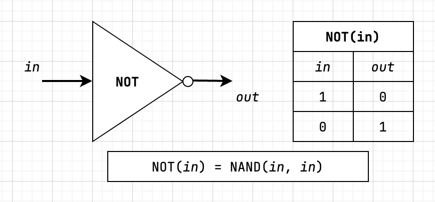
NOT
A NOT gate with a single input is also referred to as a "converter". The NOT gate negates the input, so input of 1 returns 0 and input of 0 returns 1.
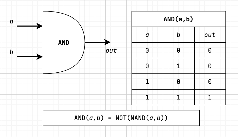
AND
The AND gate returns 1 when both inputs are 1 otherwise returns 0.
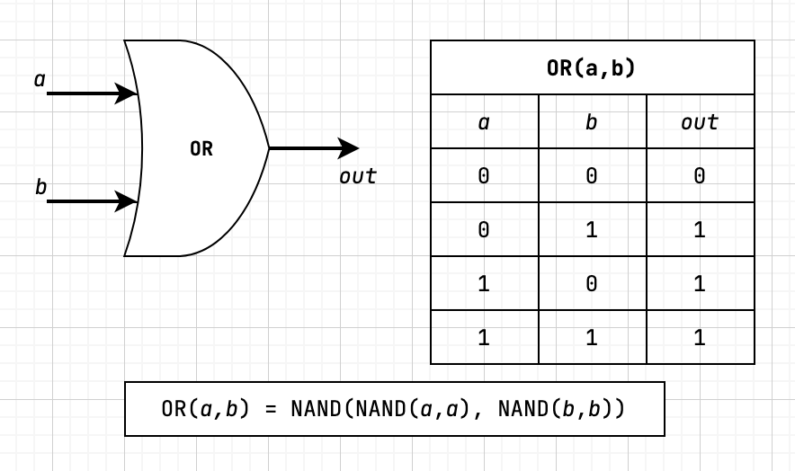
OR
The OR gate returns 1 when either of the inputs are 1 otherwise returns 0.
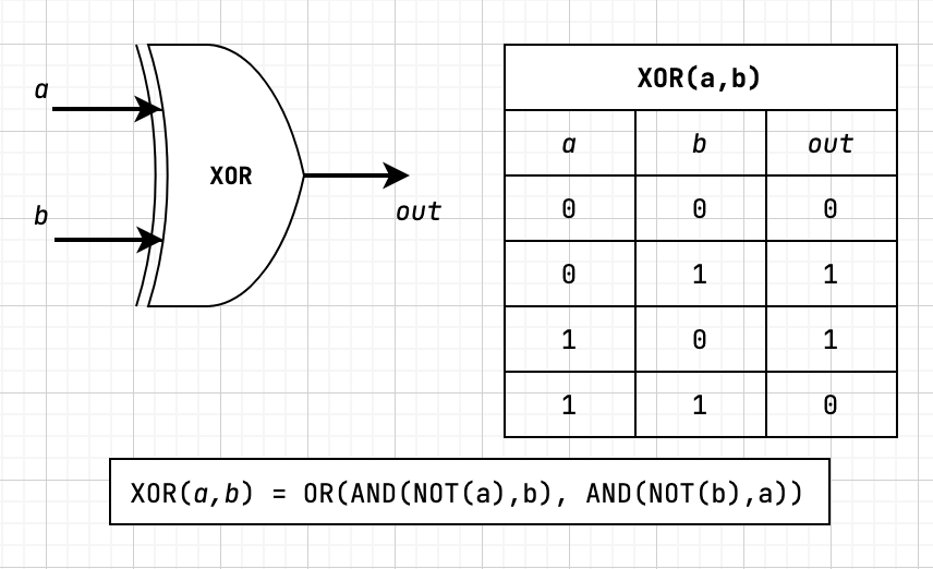
XOR
The XOR gate returns 1 when the inputs are not equal otherwise returns 0. XOR is also referred to as "exclusive or".
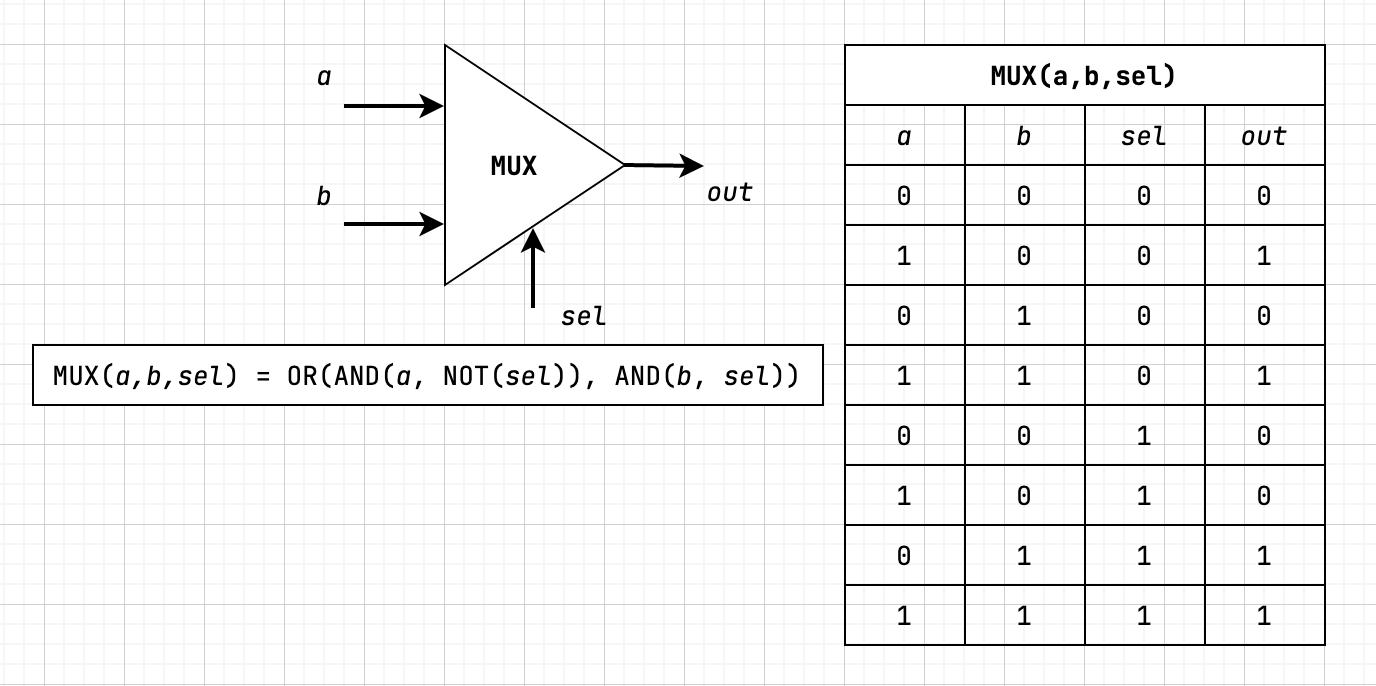
MUX (Multiplexor)
The next two gates that we'll discuss are a little different. They both have what is called a "selection bit", which is used to output one of the two input bits (known as "data bits").
The first gate that we'll be looking at is the MUX or "multiplexor" gate, which accepts two data bits, a and b, and a section bit sel. With MUX if the selector bit is 1, then the output is the b data bit otherwise the output is the a data bit.
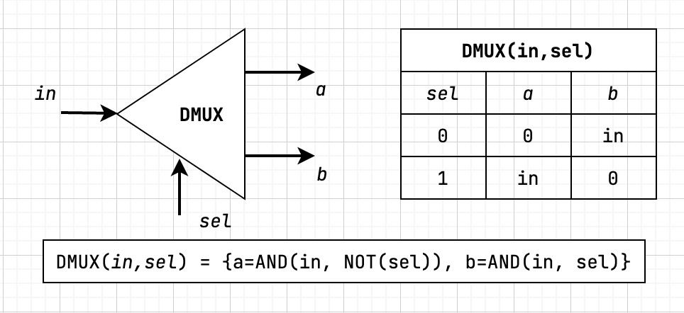
DMUX (Demultiplexor)
The DMUX or "demultiplexor" gate performs the exact opposite operation as the MUX gate. It takes a single data input, in, and a selector bit. It then outputs two bits whose values are dependent on the value of the selector. If selector is 1 then the output is {a=0, b=in} otherwise the output is {a=in, b=0}.
As you can see from the progression of diagrams, all of these gates are built from previously implemented gates. With the fundamental building blocks, we are able to create complex gates that provide all the functionality that we need for building a computer.
If you'd like to learn more about this, including multi-bit and multi-way variants, I would highly recommend checking out Build a Modern Computer from First Principles: From Nand to Tetris because you'll learn all of this and much more with a project-based approach.